How to Read Wiring Diagrams for Appliance Repair
Learn how to read wiring diagrams for appliance repair, trace live circuits safely, test components with a meter, and diagnose faults like a technician.
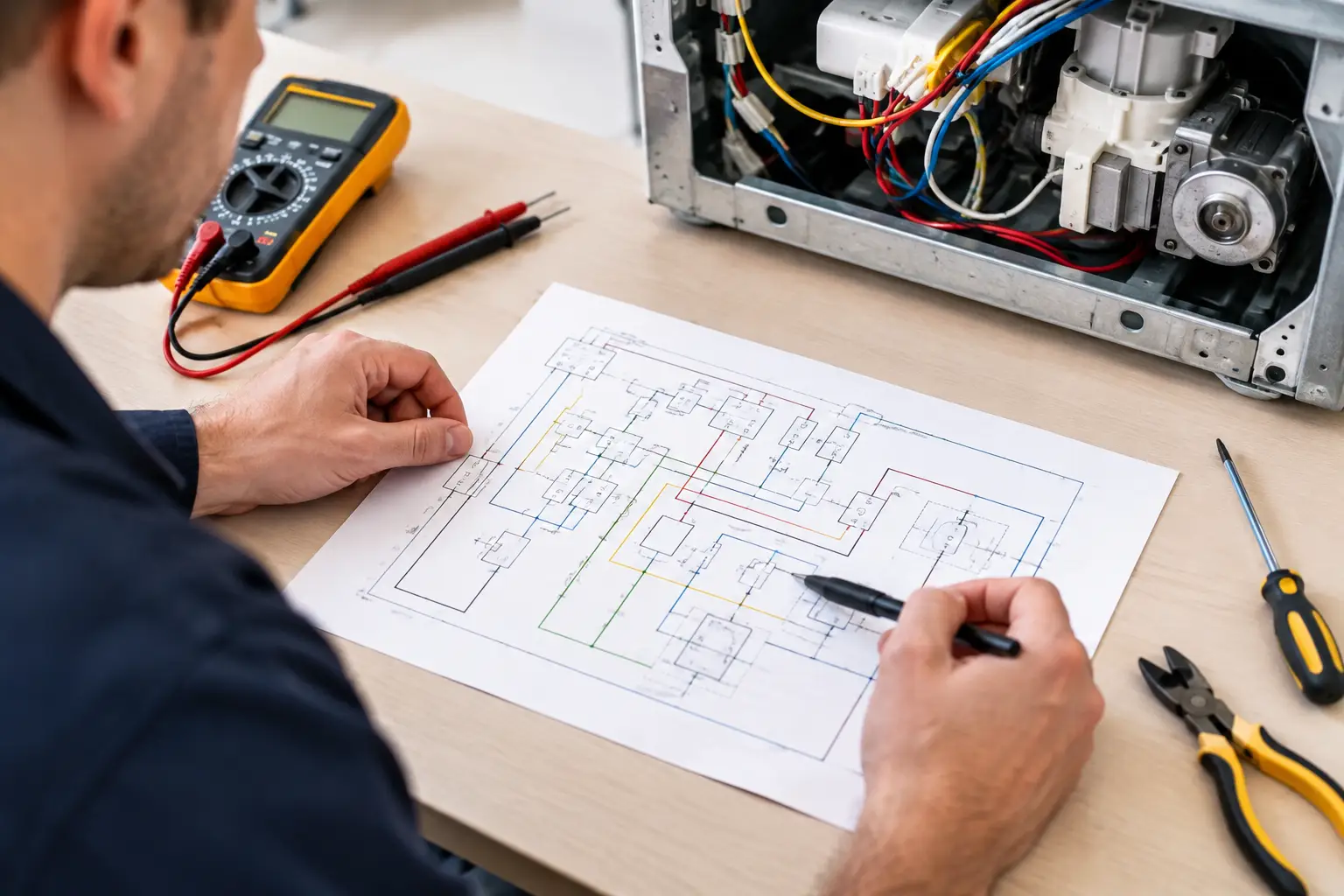
A no-cool dishwasher, a dead dryer, or a refrigerator that will not defrost can look like a major failure from the customer’s kitchen. Often, the answer is sitting on a folded wiring sheet behind the toe kick, inside the console, or taped to the cabinet. Learning how to read wiring diagrams turns that sheet from intimidating paperwork into a paid diagnostic tool.
A wiring diagram does not repair an appliance for you. It gives you a map of the circuit so you can stop guessing, test with purpose, and explain the failure with confidence. That difference matters when you are building a career where accurate first-visit diagnosis protects your time, your parts budget, and your reputation.
Start Safe Before You Start Tracing
Wiring diagrams represent electrical paths, not safe working conditions. Before removing panels or placing meter leads, disconnect power when the test does not require voltage. Use lockout/tagout practices when working around equipment that could be energized by another person, and discharge high-voltage capacitors according to the manufacturer procedure. Microwaves require additional high-voltage safety knowledge and should never be treated like a standard 120-volt appliance.
When a live-voltage test is necessary, inspect your meter, leads, and probes first. Confirm the meter is set to the correct function and range, then prove it on a known voltage source before and after testing. This is not extra caution for its own sake. A bad meter lead, incorrect setting, or assumed reading can put a technician at risk and send the diagnosis in the wrong direction.
What a Wiring Diagram Actually Shows
Most appliance wiring diagrams show how power travels from the supply into switches, control boards, loads, and neutral or return paths. A load is the component doing work, such as a heating element, motor, valve, compressor relay, fan motor, or drain pump.
The diagram may look different from the appliance in front of you. It is usually not drawn to match the physical location of components. A door switch might appear beside a control board on paper even though it sits several feet away in the machine. Read it as an electrical story, not a picture of the cabinet.
A complete tech sheet often includes more than one drawing. The wiring diagram shows circuit connections. A schematic simplifies the electrical logic. A component locator identifies where parts are physically installed. A timing chart, error-code table, or service-mode instructions may support the diagnosis. Use the page that answers the question you are trying to solve.
Learn the symbols before following the circuit
Symbols vary somewhat by manufacturer, but the function stays consistent. A switch opens or closes a path. A relay uses a low-power signal to control a higher-power circuit. A resistor limits current. A thermistor changes resistance with temperature. A fuse or thermal cutoff opens permanently when it experiences an overheat event.
Wire labels are equally valuable. You may see color abbreviations such as BK for black, WH for white, RD for red, BL for blue, or GN for green. Numbers beside wires often identify the circuit or connector cavity. A wire marked BL/WH is generally blue with a white stripe. Do not rely only on color, especially on older units or harnesses that have been repaired. Confirm the terminal label and connector position too.
How to Read Wiring Diagrams One Circuit at a Time
The fastest way to get lost is trying to understand every line at once. Start with the customer complaint and isolate the circuit related to that complaint.
If a dryer tumbles but has no heat, begin at the heating circuit. Find the incoming L1 and L2 supply, then trace through the timer or control relay, thermal cutoff, high-limit thermostat, heating element, and back to the opposite supply leg. On a 240-volt electric dryer, the motor can run on 120 volts while the heating circuit has lost the second leg. That detail prevents a common and expensive misdiagnosis.
If a dishwasher will not fill, follow the water-valve circuit. Identify where line voltage originates, what safety switches or control-board outputs are in series, and where neutral returns. If the control is calling for water but voltage never reaches the valve, work backward through the open point. If full voltage reaches the valve and the valve does not open, the valve or its water supply becomes the next focus.
This is the repeatable process:
- Identify the power source and the expected voltage.
- Find the load that should operate.
- Trace every component and connection between source and load.
- Identify the control or safety devices that can interrupt the path.
- Test at logical checkpoints to locate where the expected voltage, continuity, or signal disappears.
The diagram tells you what should be true. Your meter confirms what is true on that appliance, in that customer’s home, on that service call.
Series and parallel paths change the diagnosis
Components wired in series share one path. If one switch, fuse, connector, or wire opens, the entire circuit stops. Thermal fuses, door switches, float switches, and high-limit devices are often placed in series because they are designed to interrupt operation under specific conditions.
Parallel branches receive power independently. A refrigerator may have separate branches for interior lights, evaporator fan operation, defrost heat, and control logic. One failed branch does not automatically mean the rest of the appliance is dead.
Look carefully at line crossings. A crossing with a connection dot means the conductors join. Lines that simply cross without a dot are usually separate. Misreading that one detail can create a diagnosis that makes no electrical sense.
Use Connector References Like a Field Technician
Modern appliances rely heavily on control boards and multi-pin harnesses. The wiring diagram may label a connection as J4-3, CN2, P5, or similar. This means the test point is not just "somewhere on the board." It identifies a specific connector and terminal position.
Match the diagram reference to the board printing, harness label, or tech-sheet connector view. Then inspect the real-world connection for backed-out terminals, corrosion, overheated plastic, broken locking tabs, and harness damage near hinges or vibration points. A board can send the correct output while a damaged connector prevents that output from reaching the load.
When back-probing a connector, avoid spreading terminals with oversized probes. Use appropriate pin probes and support the connector so you do not create an intermittent failure while testing. Good diagnostics should not introduce a new problem.
Read Voltage Drops, Not Just Continuity
Continuity testing is useful with power disconnected, but it has limits. A circuit can show continuity and still fail under load because of a weak connector, carbonized relay contact, or damaged wire strand. That is where voltage-drop testing earns its place.
For example, if a heating element should receive 240 volts, measure across the element terminals when the appliance is calling for heat. If you read the correct voltage and the element has proper resistance, the issue may be mechanical, airflow-related, or tied to the operating conditions. If you read zero volts, measure from each element terminal to the appropriate supply reference and trace the missing side.
Do not condemn a control board just because a component is inactive. First prove the board has the correct incoming power, required door or safety inputs, and operating command. Control boards fail, but loose terminals, broken harnesses, failed safety devices, and incorrect supply voltage are often more common.
Build a Diagnostic Story You Can Defend
Professional troubleshooting is not a collection of random meter readings. It is a documented chain of evidence. Write down the complaint, model number, error codes, test conditions, expected readings, actual readings, and failed point in the circuit. That documentation supports a clear customer explanation and protects you when a job requires a return visit.
Say, "The control is sending 120 volts to the drain pump, but the pump winding is open," rather than, "The pump is bad." The first statement shows the customer why the recommendation is justified. It also creates a clean job ticket for parts ordering and future service history.
Wiring diagrams become easier through repetition. Start with familiar circuits such as dryer heat, washer drain, dishwasher fill, and refrigerator fan motors. Then move into thermistor diagnostics, inverter-driven compressors, induction cooking circuits, and board communication systems. The layouts change, but the core question remains the same: where does the electrical path stop doing what it is supposed to do?
If you want structured practice with real appliance scenarios, explore Appliance Repair Academy training content and use the Appliance Repair AI diagnostic app alongside hands-on meter work. The goal is not to memorize every diagram. It is to become the technician who can trace the circuit, prove the failure, and move the job forward.